Thermal · Fluids · CFD
Aircraft Environmental Control System
Avionics-cooling ECS developed from first-principles sizing through robust design selection and 3D CFD validation.
Mechanical Engineering · Aerospace · Analysis · Manufacturing
Mechanical Engineering student at Concordia University building aerospace-focused projects in aircraft systems, controls, structural dynamics, thermal-fluid design, CFD, and manufacturing.
Selected engineering work
Open any project for the full engineering approach, plots, validation, trade studies, and final results.
Thermal · Fluids · CFD
Avionics-cooling ECS developed from first-principles sizing through robust design selection and 3D CFD validation.
Controls · Flight Dynamics
Boeing 747 longitudinal-control study with a corrected two-input aircraft model, actuator-constrained PID/LQI control, command shaping, and numerical robustness validation.
Structures · FEA · Aeroelasticity
Parametric CAD/FEA study of modal behavior, static loading, geometry, material, root stiffness, and preliminary flutter screening.
Experience
Manufacturing Team Member
Manufacturing Assistant
Technical skills
Education
Expected 2028
Mechanical engineering studies supported by hands-on aerospace projects in controls, thermal-fluid systems, structural dynamics, and manufacturing.
Training & Certifications
Technical software training through MathWorks and safety training through Concordia University.
Modeling and simulation training across MATLAB, Simulink, and Simscape.

Completed the 5-course “Control System Design with MATLAB and Simulink” learning path.

Completed the 5-course “Build Simulink Proficiency” learning path.
Laboratory, hazardous-materials, and workplace safety training.
Resume
Mechanical Engineering B.Eng. student at Concordia University with project work in aerospace controls, thermal-fluid systems, structural dynamics, FEA, CFD, and manufacturing.
B.Eng. Mechanical Engineering · Projects, experience, and technical skills
Contact
Thermal · Fluids · CFD · System Design
A preliminary avionics-cooling ECS developed from first-principles thermal sizing through integrated duct/fan/heat-exchanger modeling, robust design selection, off-design assessment, and independent 3D CFD validation.
The objective was to design and evaluate a closed recirculating-air system for cooling an aircraft avionics/electronics compartment. The model quantified thermal load, required airflow, duct pressure losses, heat-exchanger performance, fan power, robustness, and off-design behavior while maintaining the compartment-temperature requirement.
The avionics-side air recirculates through a fan, duct network, and air-to-air heat exchanger before returning to the compartment. A separate external-air stream removes heat through the cold side of the heat exchanger without mixing with the avionics air.
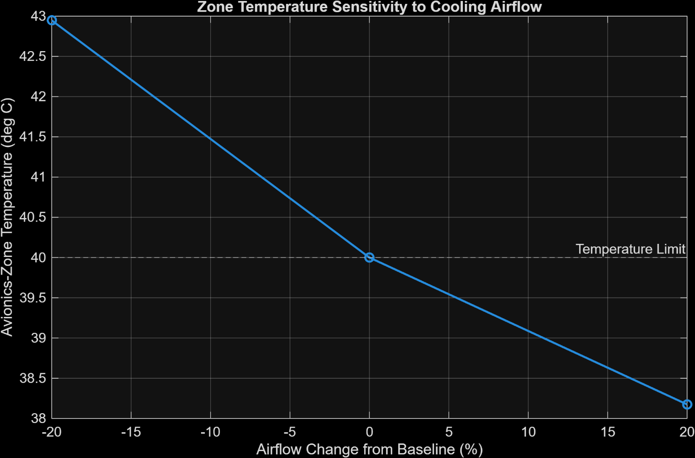
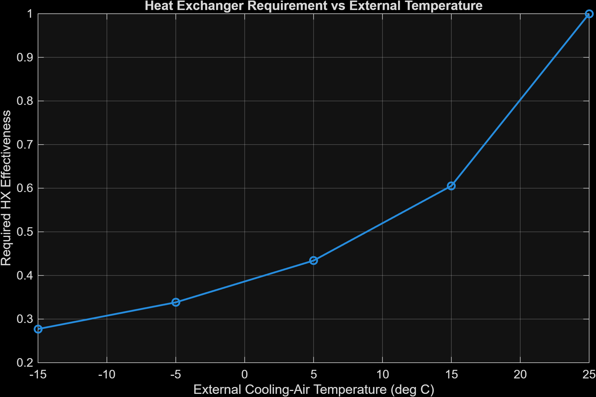
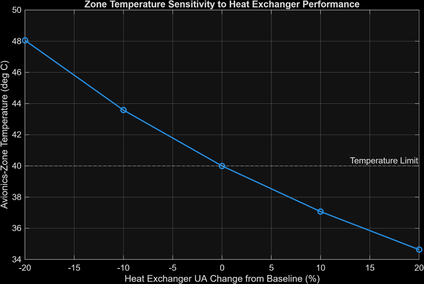
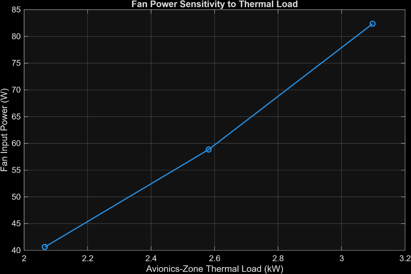
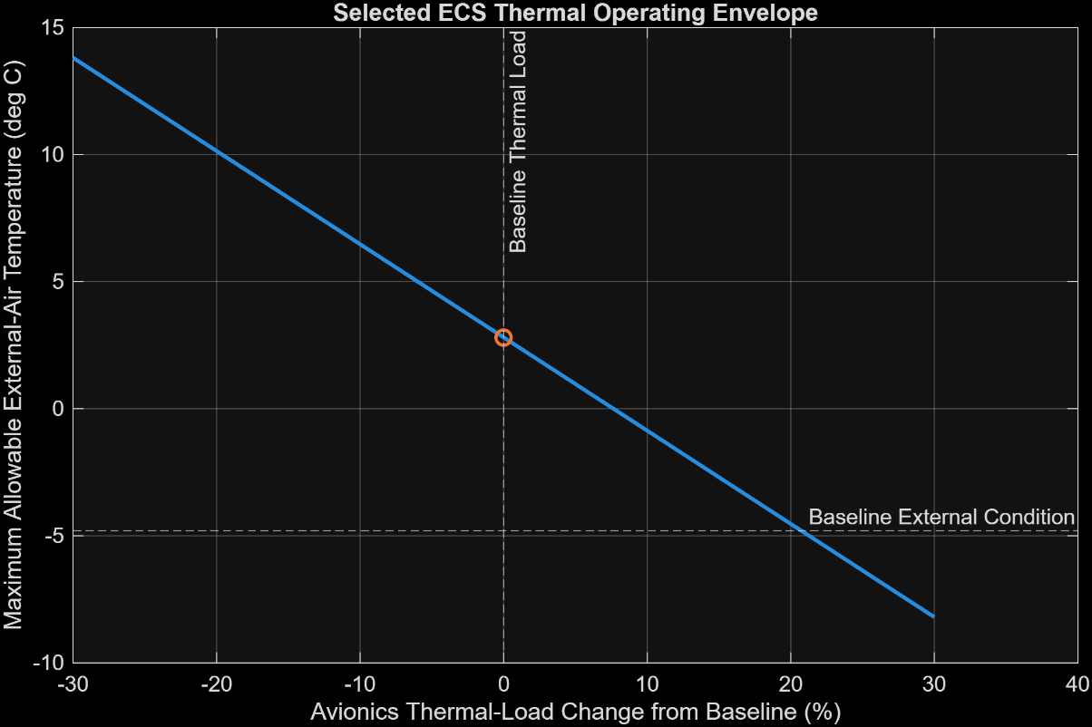
The system model was used to evaluate sensitivity to recirculation airflow, external-air temperature, heat-exchanger performance, thermal load, and other design variables. Swipe through the plots below.
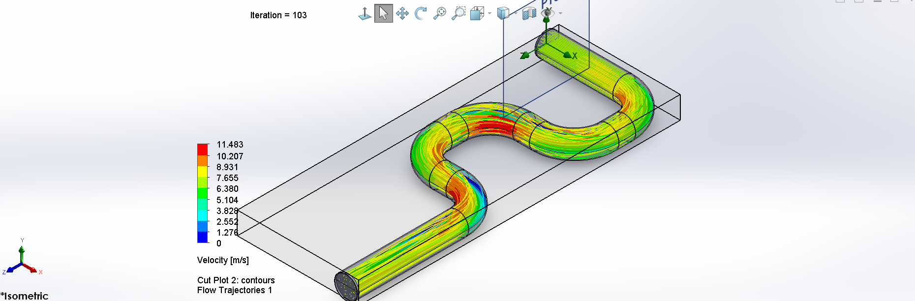
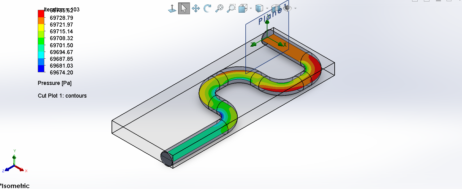
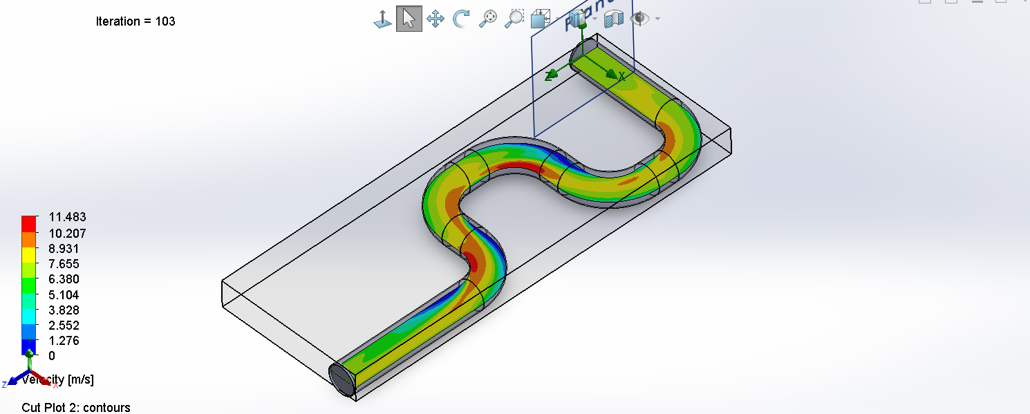
The selected duct network was evaluated in SOLIDWORKS Flow Simulation to independently check the one-dimensional pressure-loss model and inspect local velocity and pressure behavior through the bends.
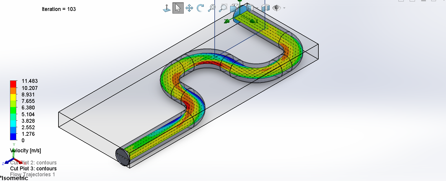
The selected robust design used a 0.200 m duct, 0.18838 kg/s recirculation flow, and 102.22 W/K heat-exchanger conductance. Its conservative fan-sizing requirement was 143.96 Pa at about 56.89 W input. The design predicted 32.40°C nominal zone temperature and 39.21°C under the defined +10% thermal-load / −10% effective-UA stress case, leaving 0.795°C margin to the 40°C limit.
Limitation: Standalone air-to-air cooling is insufficient for representative warm-ground operation; supplemental cooling or an additional heat sink would be required.
Updated 39-page final report covering first-principles thermal sizing, robust design selection, off-design operating limits, analytical/CFD pressure-loss validation, and the warm-ground feasibility check.
Open reportControls · Flight Dynamics · MATLAB · Simulink
A Boeing 747 longitudinal-flight-control study progressing from open-loop dynamics through reference-shaped PID and full-state LQI control, with model-validity correction, nonlinear elevator constraints, frequency-domain robustness assessment, and 500-trial aerodynamic uncertainty testing.
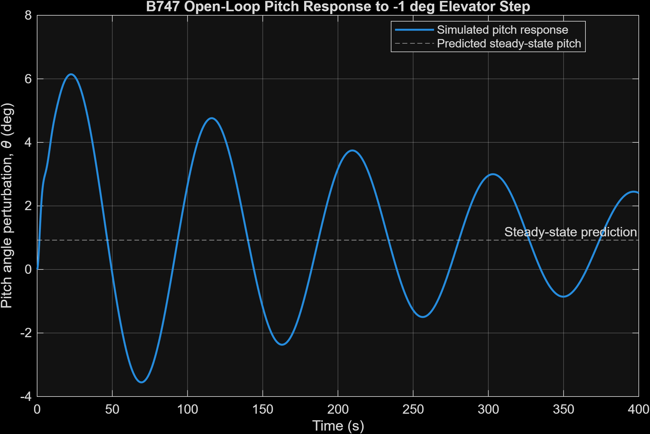
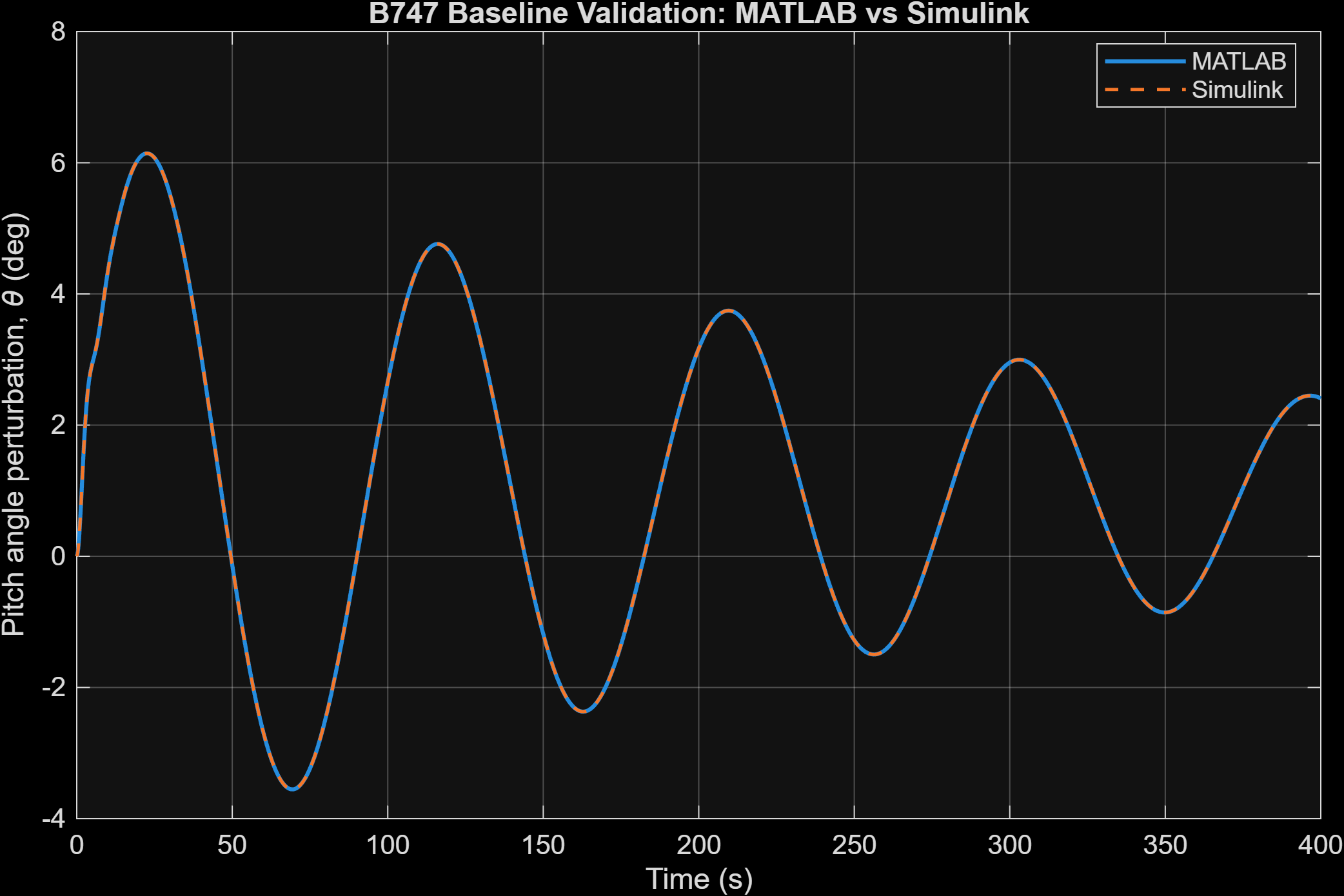
The project reconstructed a documented Boeing 747 linear small-perturbation longitudinal model at Mach 0.80 and 40,000 ft and identified the short-period and phugoid modes. A later model-validity audit showed that the original elevator-only long-duration simulations could drive forward-speed departure to about 15.6% of trim. Restoring the documented thrust-control channel and adding a simplified airspeed-hold augmentation reduced the maximum nominal forward-speed departure to 0.227% of trim for PID and 0.194% for LQI.
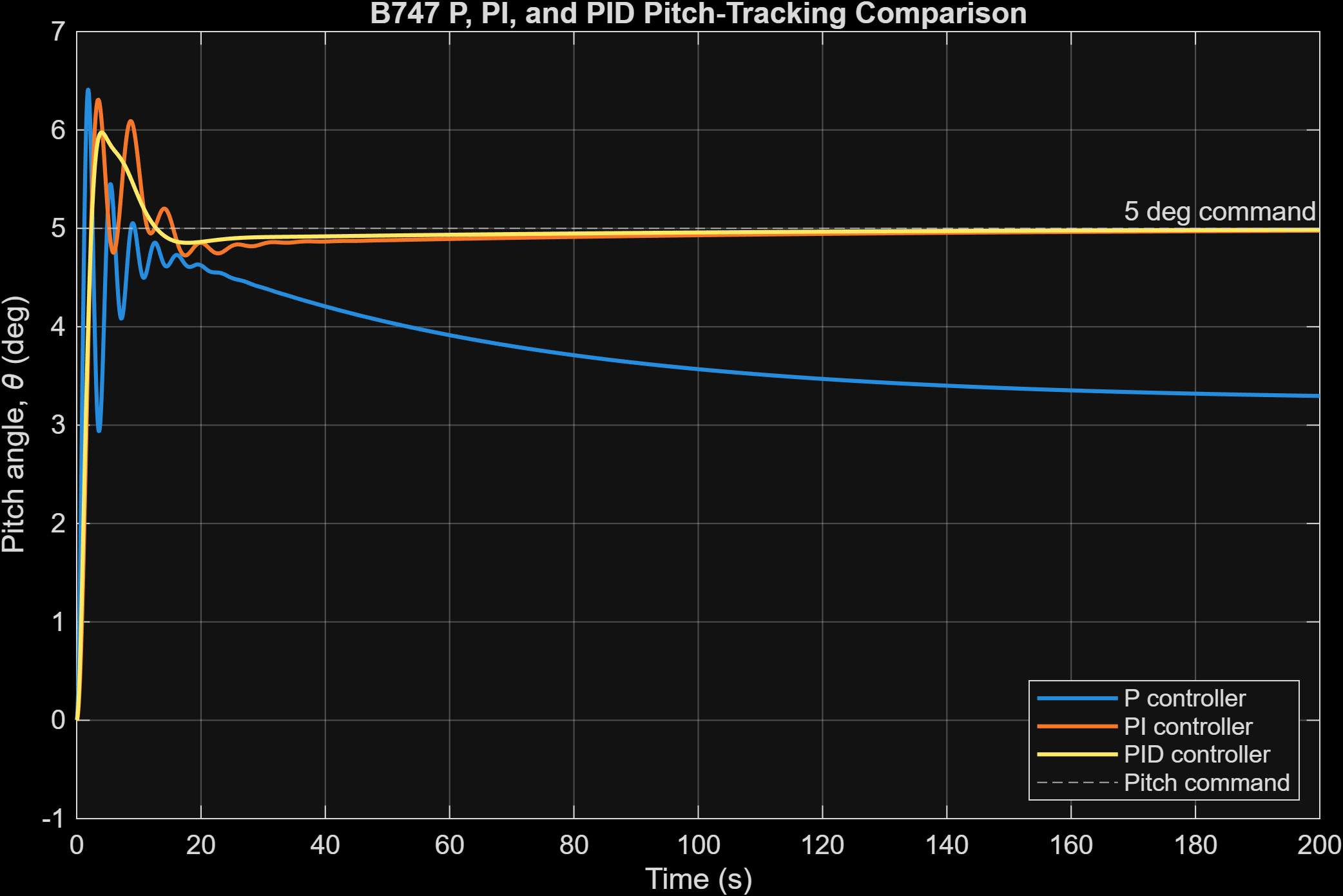
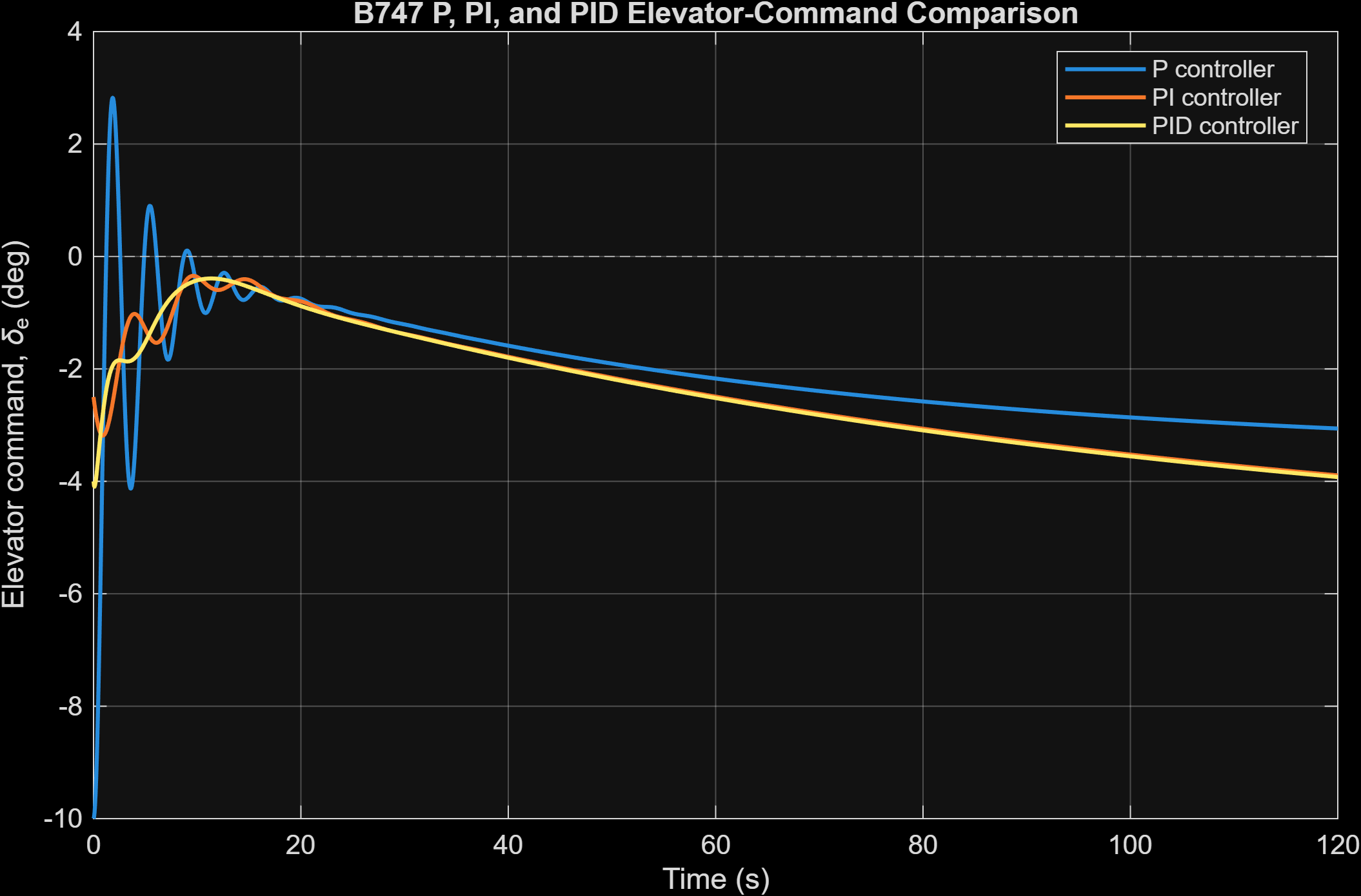
P, PI, and filtered-PID controllers were developed first, then evaluated with a nonlinear elevator actuator using travel and 37°/s rate limits. An unshaped 5° command requested about 185°/s of elevator motion, so a 0.10 s first-order command shaper was introduced. The final reference-shaped PID reduced requested rate to 31.57°/s and achieved 15.33% overshoot with 14.07 s settling time.
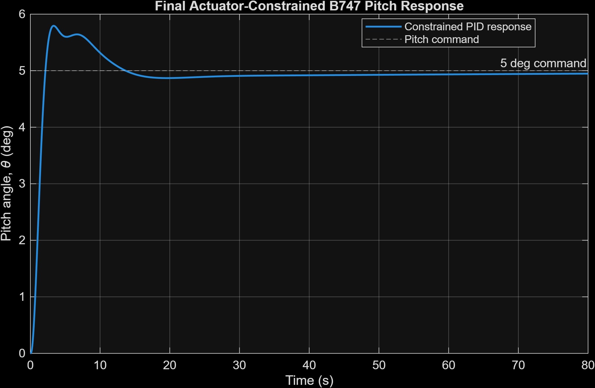
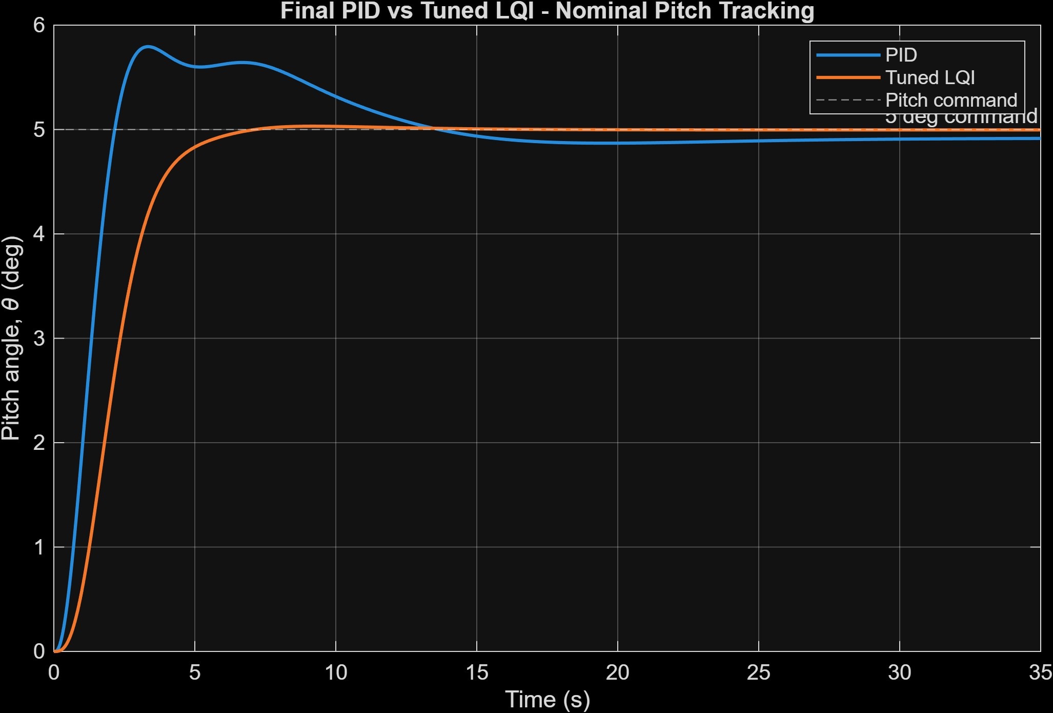
The final corrected-architecture comparison used the same aircraft, thrust/airspeed augmentation, and nonlinear actuator assumptions for both controllers. The tuned LQI achieved 0.682% nominal overshoot and 5.58 s settling with only 5.32°/s requested elevator rate, versus 15.33%, 14.07 s, and 31.57°/s for the reference-shaped PID.
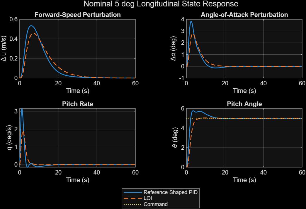
Final validation included 20% reduced elevator effectiveness, 2° and 5° step commands, a 5° two-second ramp, internal-state checks, frequency-domain robustness, and 500 reproducible ±10% aerodynamic-model uncertainty trials per controller. All 500 LQI trials satisfied every project criterion. PID remained stable and tracked all 500 cases, with 475/500 satisfying every criterion; the remaining 25 exceeded only the selected 20% overshoot threshold. A +2° control-channel disturbance case was retained as supplementary evidence.
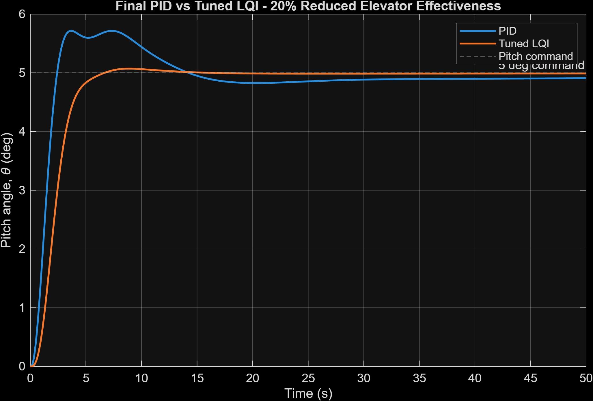
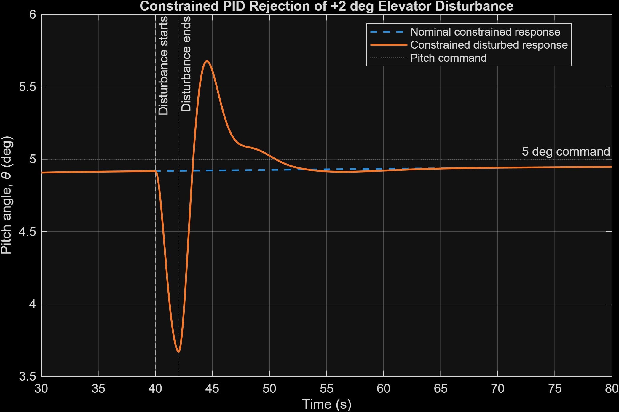
The tuned LQI was the highest-performing controller in the final simulation study, while the reference-shaped PID remained a validated lower-complexity benchmark. The values below are from the corrected final architecture in the updated report.
Final comparison: Tuned LQI achieved 0.682% overshoot and 5.58 s settling versus 15.33% and 14.07 s for the reference-shaped PID, with substantially lower actuator-rate demand. LQI assumes full-state feedback; no state estimator was developed.
Updated 78-page final report covering model reconstruction, thrust/airspeed validity correction, reference-shaped PID, tuned LQI, actuator constraints, uncertainty testing, frequency-domain robustness, and final validation.
Open reportStructures · FEA · Aeroelasticity
Validated structural, modal, and preliminary aeroelastic study of a trapezoidal rocket fin, combining SOLIDWORKS FEA, analytical checks, controlled parametric trade studies, and two-level aerodynamic load screening.
The 3 mm 6061-T6 aluminum baseline was checked three ways: modal FEA, a simplified analytical cantilever estimate, and mesh refinement. SOLIDWORKS predicted 136.19 Hz for first bending and 381.54 Hz for first torsion; the analytical bending estimate was 108.87 Hz, about 20.06% lower as expected for the simplified beam model. Mesh refinement changed the torsional result by only about 0.005%.
Thickness, span, material, root-support stiffness, and sweep were varied systematically. Span strongly affected flexibility, while the corrected constant-area sweep study showed that isolated tip-chord offset changed the first two natural frequencies by less than 1%. A first-order bonded-joint stiffness estimate of 1×10¹⁰ N/m produced a 128.64 Hz lowest mode, within about 5.5% of the fully fixed reference. Simplified carbon/epoxy screening gave the best stiffness-to-mass result, but was not treated as a laminate-ready design.
The static study used two load levels. The original p = q case was retained only as a conservative unit-coefficient reference for consistent speed and thickness comparisons. At 100 m/s it produced 31.50 MPa maximum stress and 1.716 mm displacement. A more physical finite-wing screening model tied equivalent pressure to angle of attack: the 5° case at 100 m/s used 960 Pa and was validated in SOLIDWORKS at 4.94 MPa maximum stress and 0.269 mm displacement.
The baseline bending and torsional modes were separated by a frequency ratio of about 2.80. Reduced-frequency analysis connected those structural modes to flight speed, but no flutter speed is claimed: structural damping, aerodynamic damping, unsteady aerodynamic stiffness, and a coupled flutter eigenvalue solution were outside the study.
Among the fully evaluated aluminum thicknesses, the 3 mm fin was retained as the best-balanced configuration. The 4 mm design reduced stress and deflection further but increased mass by 33.3%, while the 2 mm design was substantially more flexible.
Scope limit: The aerodynamic loads remain equivalent-pressure screening models, the baseline root is idealized, and no formal coupled flutter solution or fatigue-life prediction is claimed.
Updated 28-page report covering modal validation, mesh convergence, controlled geometry/material/root-stiffness studies, two-level aerodynamic loading, thickness tradeoffs, reduced-frequency screening, limitations, and future flutter/CFD validation work.
Open report