Engineering Problem
Design a preliminary environmental control system for an aircraft avionics/electronics compartment using a closed recirculating-air loop and a separate external cooling-air stream through an air-to-air heat exchanger.
System-Level Workflow
- Developed a traceable avionics thermal-load model and required cooling-airflow calculation.
- Modeled duct friction, fitting losses, heat-exchanger resistance, fan power, and fan heat addition.
- Sized the heat exchanger using an effectiveness-NTU approach.
- Performed multi-parameter sensitivity studies, a 50-case robust-design sweep, and off-design operating-envelope analysis.
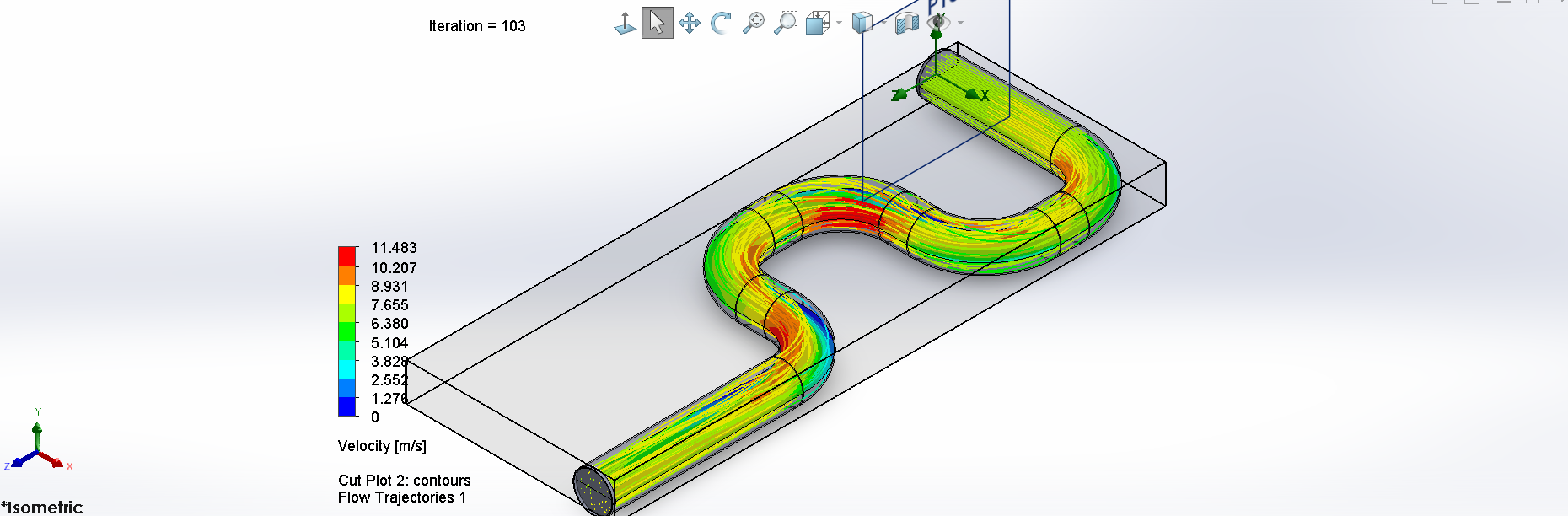
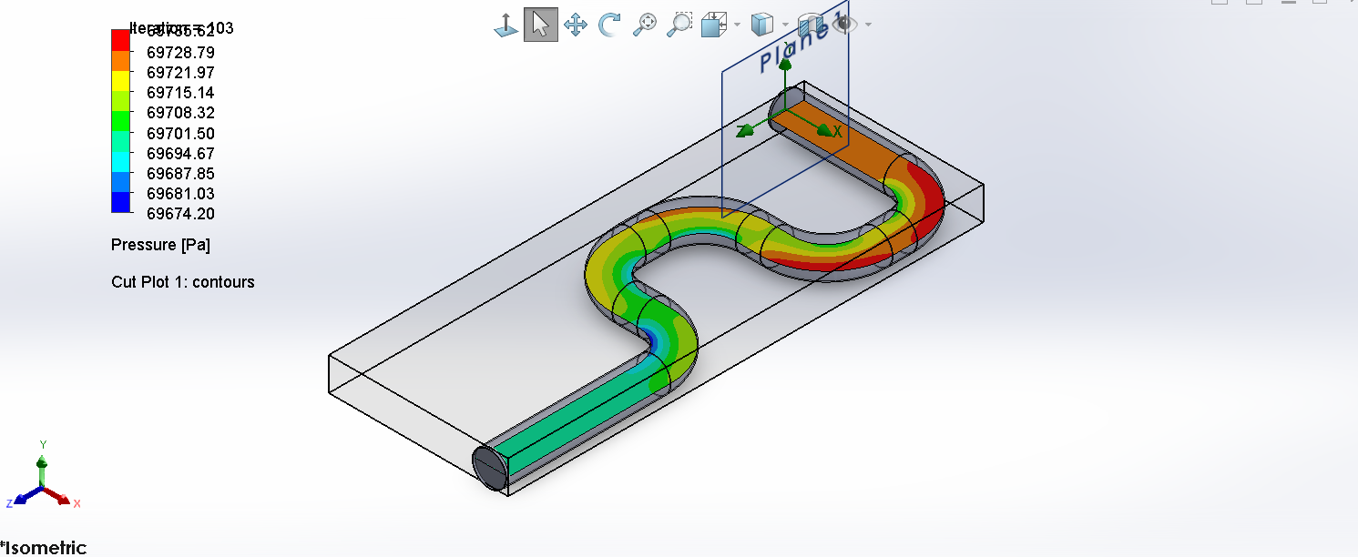
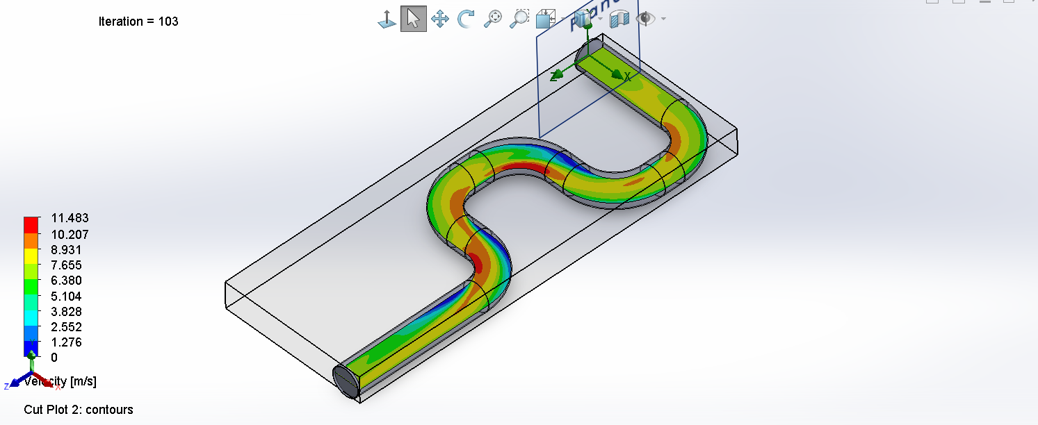
- Independently validated the selected duct network with 3D CFD and a controlled mesh-refinement study.
CFD Validation
Robust Design Result
The final design intentionally retained a conservative analytical pressure-loss basis for fan sizing even though CFD predicted lower losses for the idealized smooth long-radius geometry. The selected configuration also preserved positive thermal reserve and could tolerate approximately 20.7% additional avionics load at the baseline external condition before reaching the zone-temperature limit.
Engineering Takeaway
The project became a complete preliminary design workflow rather than a single calculation: first-principles sizing, integrated modeling, sensitivity analysis, robust configuration selection, off-design evaluation, and independent CFD validation all informed the final design freeze.
Full technical report
The complete report contains the thermal model, duct sizing, fan and heat-exchanger calculations, sensitivity studies, robust-design sweep, operating envelope, CFD validation, and final validation matrix.